5
OPERATING DISTANCE
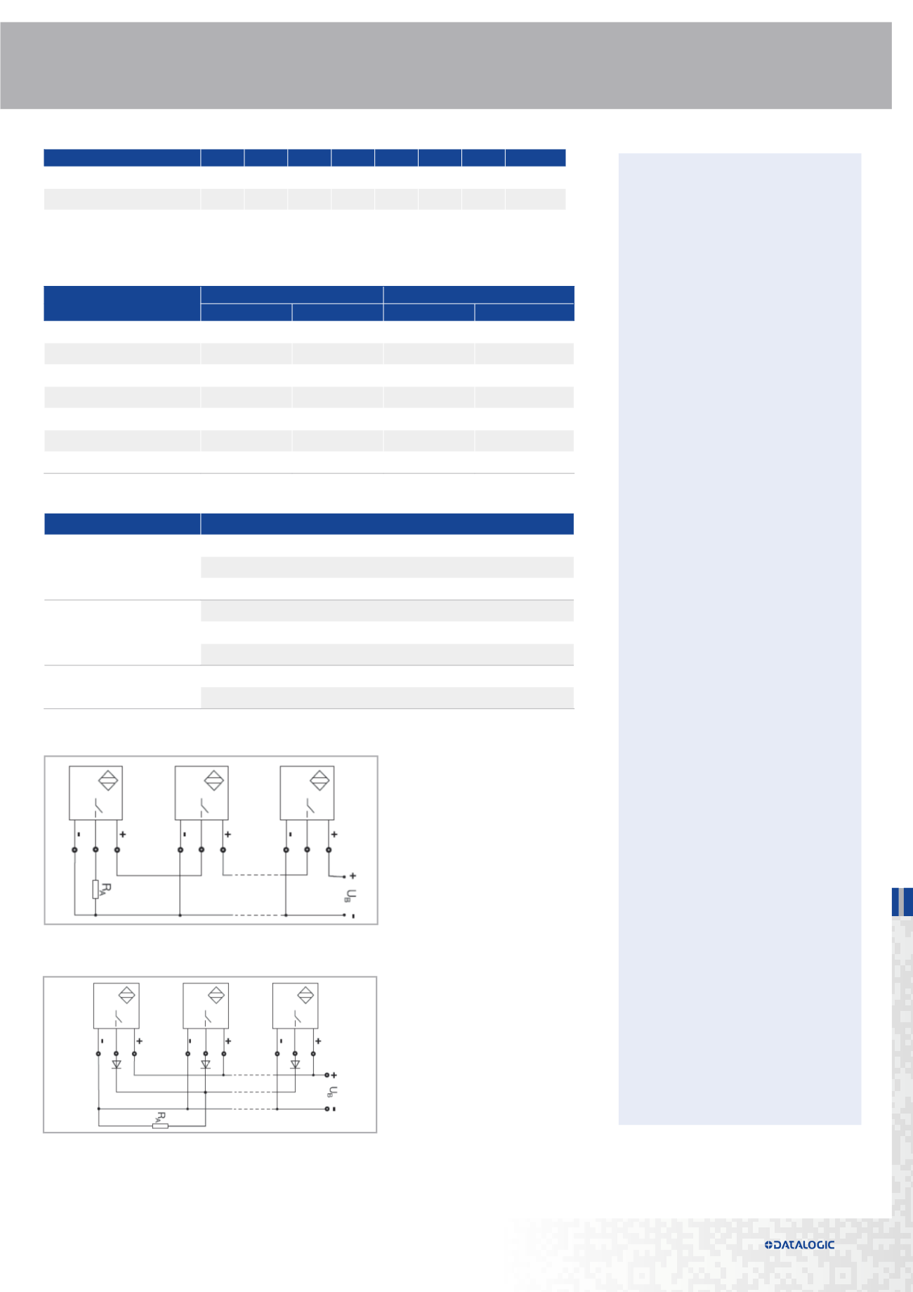
Parallel connection: the leakage current of each single sensor, when added to the other, may
accumulate and drive the load even in the absence of operated switches.
HOUSING LENGTHS
The following table shows the approximate length (mm) intervals for all categories and models
of tubular inductive sensors.
The number of inductive proximity sensors that can be connected in series or parallel is limited.
• NOMINAL VOLTAGE
Is the permissible voltage range in
which certain safe operation of the
switch is guaranteed.
• RESIDUAL RIPPLE
Is the maximum admissible ripple
of the DC supply voltage shown as
percentage to its medium value.
• MAX. OUTPUT CURRENT
It shows maximum output current a
sensor can cope with when working
steadly.
• MIN. OUTPUT CURRENT
Is the smallest load current required
for function of the switch when ON.
• RESIDUAL CURRENT
Is the current flowing through the
load when a proximity switch is not
conducting (open).
• VOLTAGE DROP
Is the voltage measured across the
load of a closed (conducting) sensor
at load current.
• START UP DELAY
Is the time from when the supply
voltage is applied, and the proximity
switch assumes the ready state.
This time may not be longer than
300 ms. During this time there
must be no fault signal longer than
2 ms.
• SWITCHING FREQUENCY
Refers to the maximum number of
switching operations per second.
• SHORT CIRCUIT PROTECTION
Is 100 A, i. e., per EN 60947-5-2
the power supply during testing in
short circuit mode must be able to
provide at least 100 A for a short
duration. This current is prescribed
in the standard in order to test.
• PROTECTION AGAINST INVERSION OF
POLARITY
Available in DC supplied type, it
prevents the sensor from being
damage when supply cables are
incorrectly connected.
• INDUCTIVE LOAD PROTECTION
It protects sensor output in
presence of high inductive loads.
This protection is performed by a
diode or zenner diode.
This problem is more relevant in versions AC 2-wire, because of the high voltages and currents supplied
to the sensor. For this type of connection you should use a 3-wire sensors working in DC.
ELECTRICAL PARAMETERS
MODELS
STANDARD
SHORT
connector
cable
connector
cable
M4
---
25
---
---
M5
40
20…25
---
---
M6,5
53…63
46…55
50…54
40…44
M8
52…73
44…55
48…57
40…44
M12
68…72
58…64
48…54
42…48
M18
73…82
70…78
56…65
47…56
M30
74…85
70…82
56…68
49…56
MODEL
M4
M5 M6,5 M8 M12 M18 M30 SQUARE
DIAMETER (mm)
4
5
6,5
8
12
18
30
8x8; 40x40
OPERATING DISTANCE (mm)
0,8
0,8…1,5 1…3
1,5…3 2…8
5…14 10…20 1,5…30
TYPE
description
2-3 WIRES
Work with sinking or sourcing devices
Vdc, Vac and NAMUR versions
Higher leakage current
3 WIRES
Must select PNP or NPN, NC or NO version
10-30 Vdc version
Low leakage current
4 WIRES
Programmable output
PNP/NPN and NC/NO in one device
Wires


